9.2.3. beagle
This BSP supports four variants, beagleboardorig (for the original BeagleBoard), beagleboardxm (for the BeagleBoard-xM), beaglebonewhite (for the original BeagleBone) and beagleboneblack (for the BeagleBone Black). The beagleboneblack should also work for the PocketBeagle.
Currently the only distinction in the BSP are between the beagleboards and the beaglebones, but the 4 names are specified in case hardware-specific distinctions are made in the future, so this can be done without changing the usage.
Note that the beagleboards are not well tested because the hardware isn’t available any more. Expect that some drivers won’t work out of the box.
The basic hardware initialization is not performed by the BSP. A boot loader with device tree support must be used to start the BSP, e.g., U-Boot.
9.2.3.1. Boot via U-Boot
To boot via uboot, the ELF must be converted to a U-Boot image like below:
arm-rtems6-objcopy hello.exe -O binary app.bin
gzip -9 app.bin
mkimage -A arm -O linux -T kernel -a 0x80000000 -e 0x80000000 -n RTEMS -d app.bin.gz rtems-app.img
All beagles have memory starting at 0x80000000 so the load & run syntax is the same.
9.2.3.1.1. Getting the Device Tree Blob
The Device Tree Blob (DTB) is needed to load the device tree while starting up the kernel. We build the dtb from the FreeBSD source matching the commit hash from the libbsd HEAD of freebsd-org. For example if the HEAD is at “19a6ceb89dbacf74697d493e48c388767126d418” Then the right Device Tree Source (DTS) file is: https://github.com/freebsd/freebsd/blob/19a6ceb89dbacf74697d493e48c388767126d418/sys/gnu/dts/arm/am335x-boneblack.dts
Please refer to the Device Tree to know more about building and applying the Device Trees.
9.2.3.1.2. Writing the uEnv.txt file
The uEnv.txt file is needed to set any environment variable before the kernel is loaded. Each line is a u-boot command that the uboot will execute during start up.
Add the following to a file named uEnv.txt:
setenv bootdelay 5
uenvcmd=run boot
boot=fatload mmc 0 0x80800000 rtems-app.img ; fatload mmc 0 0x88000000 am335x-boneblack.dtb ; bootm 0x80800000 - 0x88000000
9.2.3.1.3. Booting from SD
You can either use the U-Boot that is on the on-board eMMC of the BeagleBone.
For that, copy the generated rtems-app.img, the am335x-boneblack.dtb
device tree and the uEnv.txt to a FAT formatted SD card. Any recent enough
U-Boot will pick up the uEnv.txt and boot based on that.
If you want to boot purely from SD card (you have to clear the on-board eMMC for
that) or if you want to write the application to the eMMC, you additionally need
the MLO and u-boot.img on your SD card. You can get these either by
building U-Boot yourself. Or you an get them from one of the pre-build images
that you can download from beagleboard.org.
9.2.3.1.4. Booting via Network
The Beagle can also be booted via a TFTP server. To do that using an U-Boot console on the BeagleBones, use the following commands:
uboot# setenv ipaddr 192.168.12.20
uboot# setenv serverip 192.168.12.10
uboot# echo starting from TFTP
uboot# tftp 0x88000000 am335x-boneblack.dtb
uboot# tftp 0x80800000 rtems-app.img
uboot# dcache off ; icache off
uboot# bootm 0x80800000 - 0x88000000
The BeagleBoards use Ethernet over USB. Therefore the commands are a bit different. Note that these commands haven’t been tested recently and you might have to add a devicetree similar to the BeagleBone:
uboot# setenv serverip 192.168.12.10
uboot# setenv ipaddr 192.168.12.62
uboot# setenv usbnet_devaddr e8:03:9a:24:f9:10
uboot# setenv usbethaddr e8:03:9a:24:f9:11
uboot# usb start
uboot# echo starting from TFTP
uboot# tftp 0x80800000 rtems-app.img
uboot# dcache off ; icache off
uboot# bootm 0x80800000
9.2.3.2. Drivers
TODO(These drivers are present but not documented yet):
Clock driver.
Network Interface Driver.
SDcard driver.
GPIO Driver.
Console driver.
PWM Driver.
RTC driver.
9.2.3.2.1. I2C Driver
The Beagle i2c initialization is based on the device tree. To initialize a i2c device, the user has to enable the respective node in the device tree using overlays.
For registering an I2C device with a custom path (say /dev/i2c-eeprom) an overlay has to be provided. The overlay must add an additional attribute rtems,path with the custom path as value to the respective i2c node.
For example,
/dts-v1/;

/ {
   compatible = "ti,am335x-bone-black", "ti,am335x-bone", "ti,am33xx";

   fragment@0 {
      target = <0xffffffff>;

      __overlay__ {
         compatible = "rtems,bsp-i2c", "ti,omap4-i2c";
         status = "okay";
         rtems,path = "/dev/i2c-eeprom";
      };
   };

   __fixups__ {
      i2c0 = "/fragment@0:target:0";
   };
};
The above example registers a custom path /dev/i2c-eeprom for i2c0.
9.2.3.2.2. SPI Driver
The SPI device /dev/spi-0 can be registered with bbb_register_spi_0()
For registering with a custom path, the bsp_register_spi() can be used.
The function prototype is given below:
rtems_status_code bsp_register_spi(
   const char         *bus_path,
   uintptr_t           register_base,
   rtems_vector_number irq
);
9.2.3.3. Debugging using libdebugger
RTEMS’s libdebugger requires the ARM debug resources be enabled for it to
work. The TI SOC used on the beagleboneblack board provides no access for
software to the ARM defined debug enable signal DBGEN. The signal is
negated on power up locking software out of the ARM debug hardware. The signal
can only be accessed via the JTAG interface.
The beagleboneblack BSP provides a low level solution to enable the
DBGEN signal via the JTAG interface if the board has the following
hardware modification installed. The modification requires the addition of two
small wire links soldered to the pads of the JTAG connect on the underside of
the board. A small length of fine wire, a fine tip soldering iron, some good
quality solder and a pair of fine tip pliers are required. If you are new to
soldering I suggest you find something to practice on first.
The modification details and software driver can be found in the BSP in the
file bsps/arm/beagle/start/bspdebug.c. The driver is automatically run
and the DBGEN is asserted via JTAG when libdebugger is started.
The modification is:
Locate P2 on the bottom side of the board. It is the JTAG connector pads. If you look at the underside of the board with the SD card holder to the right the pads are top center left. There are 20 pads in two columns. The pads are numbered 1 at the top left then 2 top right, 3 is second top on the left, 4 is second top to the right, then the pin number increments as you move left then right down the pads.
Connect P2 to P5.
Connect P7 to P13.
The resulting wiring is:
 1 ===  /--=== 2
 3 ===  |  === 4
 5 ===--/  === 6
 7 ===--\  === 8
 9 ===  |  === 10
11 ===  |  === 12
13 ===--/  === 14
15 ===     === 16
17 ===     === 18
19 ===     === 20
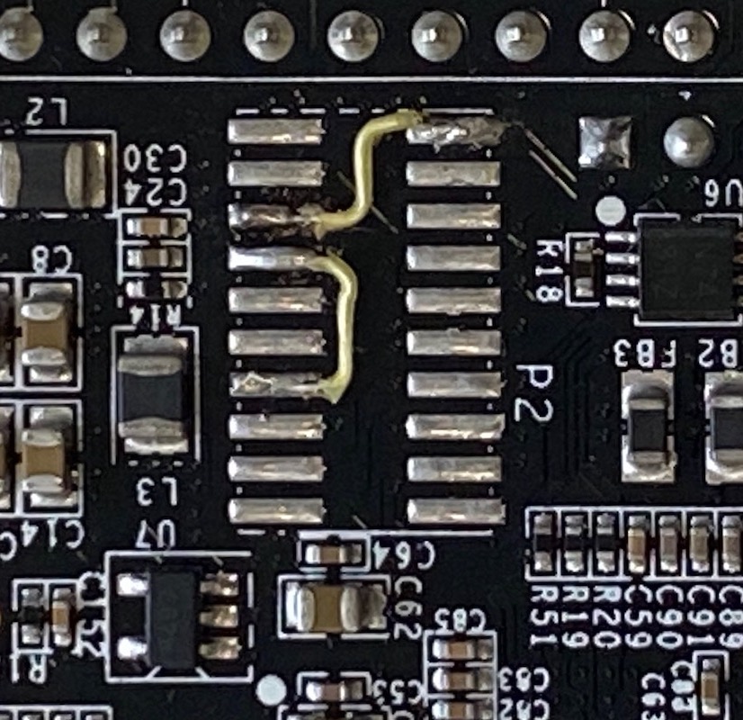
Fig. 9.1 BeagleBone Black JTAG Hardware Modification
If libdebugger fails to detect the registers open the bspdebug.c
source and change has_tdo to 1, save then rebuild and install the
BSP. This will turn on an internal feeback to check the JTAG logic. Discard
the edit once the hardware is working.
9.2.3.4. Debugging Beagle Bone Black using a JTAG debugger and gdb
Debugging a Beagle Bone Black (or variants) is also possible using a hardware JTAG debugger. The JTAG is available via P2. The footprint is for an ARM 20 pin cTI connector. That connector should be used, if it is necessary to have access to commercially available adapters.
For hand-made cables and adapters a standard 1.27mm pitch header and a 0.635mm ribbon cable can be much cheaper. But note that even if it looks compatible, it’s not the same pin out as a ARM Cortex 20 pin connector!
A lot of JTAG adapters that are working together with OpenOCD will work. There are also commercially available systems (like Segger J-Link) that work well with the Beagle. Note that the JTAG debugger has to be compatible with ARM Cortex A8. Cortex M only debuggers (like the Segger J-Link Edu Mini) won’t work.
If the debugger offers a gdb server (like OpenOCD or Segger J-Link) the following gdb start script can be used:
define reset
        echo -- Reset target and wait for U-Boot to start kernel.\n
        monitor reset
        # RTEMS U-Boot starts at this address.
        tbreak *0x80000000
        # Linux starts here.
        tbreak *0x82000000
        continue

        echo -- Disable watchdog.\n
        set *(uint32_t*)0x44e35048=0xAAAA
        while (*(uint32_t*)0x44e35034 != 0)
        end
        set *(uint32_t*)0x44e35048=0x5555
        while (*(uint32_t*)0x44e35034 != 0)
        end

        echo -- Overwrite kernel with application to debug.\n
        load
end

target remote :2331
Note that you might have to replace the monitor reset by some other command
that resets the target using your specific debugger. You also have to replace
the target remote :2331 to match the port of your gdb server.
The script expects that the Beagle Bone Black starts some application from an SD
card or from eMMC. It defines a reset command that does the following:
reset the target
let U-Boot run, initialize the base system, load an FDT and an application
break at the application entry point
disable the watchdog
overwrite the application that has been loaded by U-Boot with the application provided as an command line argument to gdb
This method has the advantage that the application is executed in nearly the same environment like it would be executed if loaded by U-Boot directly (except for the watchdog).
9.2.3.5. Debugging using a JTAG debugger and gdb without any bootcode
Note: These instructions haven’t been tested for quite some time. So you maybe have to adapt them. If possible, prefer the method with a dummy application described above.
To run RTEMS from scratch (without any other bootcode) on the beagles, you can comfortably load the executables over JTAG using gdb. This is necessarily target-specific however.
BBXM
For access to JTAG using openocd, see simscripts/bbxm.cfg.
openocd then offers access to gdb using simscripts/gdbinit.bbxm.
start openocd using bbxm.cfg
copy your .exe to a new dir and that gdbinit file as .gdbinit in the same dir
go there and start gdb: $ arm-rtems4.11-gdb hello.exe
gdb will invoke the BBXM hardware initialization in the bbxm.cfg and load the ELF over JTAG. type ‘c’ (for continue) to run it.
breakpoints, C statement and single-instruction stepping work.
beaglebone white
This has been tested with openocd and works but not in as much detail as for the BBXM yet (i.e. loading an executable from scratch).
9.2.3.6. Testing
Note: These instructions haven’t been tested for quite some time. So you maybe have to adapt them. Please update the documentation if you find bugs.
To build and run the tests for this BSP, use the RTEMS tester. The necessary software can be built with the RTEMS source builder.
To build the BSP for testing:
set CONSOLE_POLLED=1 in the configure environment, some tests assume console i/o is polled
Enable the tests during BSP configuration
Then you can run the tests:
Qemu
Linaro Qemu can emulate the beagleboard xm and so run all regression tests in software. Build the bbxm.bset from the RTEMS source builder and you will get qemu linaro that can run them. There is a beagleboardxm_qemu bsp in the RTEMS tester to invoke it with every test.
bbxm hardware
This requires JTAG, see README.JTAG. Use the beagleboardxm bsp in the RTEMS tester. It starts gdb to connect to openocd to reset the target and load the RTEMS executable for each test iteration.